Прочетете внимателно!
Technical product information
Transaction No.: 2012506/20
Vehicle judders when accelerating lightly; engine warning light sporadically on, entry P0403 - A4, A6 2.0l 4V TDI
Release date: 20-Sep-2013
Customer statement / workshop findings
a) The vehicle judders sporadically between 1400 and 2400 rpm when accelerating lightly. A brief knocking noise can occur during the juddering.
b) Engine warning light on, engine starts erratically, poor performance (emergency operation)
Sporadic entries:
P0403 exhaust gas recirculation valve malfunction
P0407 potentiometer for exhaust gas recirculation G212 – signal too small
P0408 potentiometer for exhaust gas recirculation G212 – signal too big
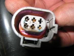
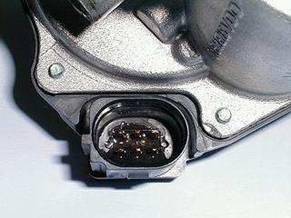
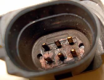
Plug and plug housing of exhaust gas recirculation valve damp:
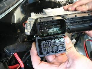
In isolated cases the humidity can get to the engine control unit plug and cause pin corrosion:
Technical background
a) Software deviation of the engine control unit control to the exhaust gas recirculation valve.
b) Humidity ingress because of incorrect shaft seal of exhaust gas recirculation valve.
Production change
---
Measure
a)
Check and if necessary update the data version.
•
See also Argumentation.
Old engine control unit
New engine control unit
New data version
SVM code
CD part number
03G 906 016 GB
03G 906 016 GB
9886
M4ZSA001
4E0 906 961 AH
03G 997 012
03G 906 016 GB
9886
M4ZSAP001
4E0 906 961 AH
03G 906 016 HS
03G 906 016 HS
9908
4F01A029
4E0 906 961 AH
03G 906 016 HQ
03G 906 016 HQ
9909
4F01A029
4E0 906 961 AH
03G 906 016 ME
03G 906 016 ME
1141
M4ZSA001
4E0 906 961 AH
03G 906 016 MF
03G 906 016 MF
1142
M4ZSA001
4E0 906 961 AH
03G 906 016 MG
03G 906 016 MG
1143
4F01A028
420 906 961 B
03G 906 016 MH
03G 906 016 MH
1144
4F01A028
4E0 906 961 AH
03G 906 016 BF
03G 906 016 BF
9970
4F01A043
8T0 906 961 L
03G 906 016 GG
03G 906 016 GG
9552
4F01A014
4L0 906 961 A
03G 906 016 GC
03G 906 016 GC
9887
M4ZSA001
4E0 906 961 AH
03G 997 056 T
03G 906 016 JD
03G 906 016 JD
9905
8E01A036
4E0 906 961 AH
03G 906 016 JB
03G 906 016 JB
9906
8E01A036
4E0 906 961 AH
03G 906 016 GN
03G 906 016 GN
9880
8E01A032
4E0 906 961 AH
03G 906 016 FC
03G 906 016 FC
9621
8E01A011
8E0 906 961 N
03G 906 016 LR
03G 906 016 LR
1838
8E01A036
4E0 906 961 AH
03G 906 016 JE
03G 906 016 JC
03G 906 016 JC
9907
8E01A036
4E0 906 961 AH
03G 906 016 CL
03G 906 016 CL
9881
8E01A032
4E0 906 961 AH
03G 906 016 FD
03G 906 016 FD
9620
8E01A011
8E0 906 961 N
•
An update with CD via self-diagnosis is not possible. If the tester cannot find the files for the update, insert the CD (see table) and perform the update as described above with the SVM code.
•
If this also not possible, contact your IT support.
•
Note: In future the Audi AG will not use CDs any more, so the an update is only possible with SVM.
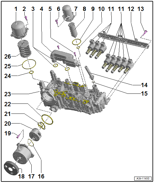
After the software update programme the exhaust gas recirculation valve as follows:
1. Disconnect battery charger and switch off ignition. The battery voltage must be between 10 - 14 V (see under engine electronics - measured value block 12 - value 3). The coolant temperature (engine temperature) must be over 5°C (see under engine electronics - measured value block 1 - value 4)
2. Switch on the ignition and within one to three seconds off again.
3. The ignition must be off for at least 45 seconds.
4. Switch on the ignition again and check the offset programmed value under engine electronics - measured values - measured value block 42 - value 1: With 0 km vehicles the value is around -16 % +-3 . For every 10000 km the offset programmed value moves about 1% towards 0. Example: running period 40000 km = -12 % +-3 % or 80000 km = -8 % +-3 %. But these are not definite figures, as the running period of the vehicle can differ from that of the component (for example if the exhaust gas recirculation valve was replaced).
The process described under 1, 2 and 3 may have to be repeated up to 10 times.
•
The entry - P0403 exhaust gas recirculation valve malfunction - is logged after the update or during the test drive (after about 500 m). The entry does not mean that the exhaust gas recirculation valve is incorrect, but that the programming has not been correctly completed. Repeat the process described under 1, 2 and 3.
Sometimes the entry - P0403 valve for exhaust gas recirculation malfunction- cannot be deleted even after programming it 10 times. If this is the case, replace the valve for exhaust gas recirculation. A programming of the exhaust gas recirculation valve is necessary after the replacement.
If after the update the vehicle still judders sporadically when accelerating lightly, proceed as follows:
- Check the air hoses after the air mass meter for leaks
- Check the boost pressure pipes for oil marks, cutting lines, cracks or damage through animal bites. Pressurise the complete boost pressure pipes with V.A.G 1687 according to repair manual (max. 0.5 bar).
If the judder still occurs on the A6 with 2.0 l TDI, fit the seal with part number 028 131 547 B between exhaust gas recirculation cooler and pipe.
b)
Check the plug and pins of the exhaust gas recirculation valve for humidity or corrosion:
If corrosion or traces of dampness are detected, replace the exhaust gas recirculation valve according to the parts catalogue. If there is humidity or corrosion in the 60 pin engine control unit plug, replace the engine control unit and fit the adapter wiring loom as follows:
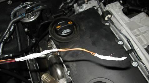
Prepare adapter wiring loom:
Wrap insulation tape around the cable ends to protect the contacts and to make the feeding through the grommet easier (illustration).
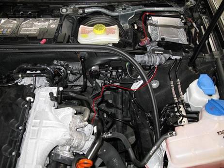
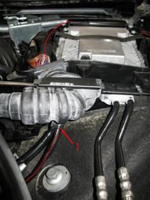
A4 (B7) LHD:
Route the adapter wiring loom following the red line.
Overview:
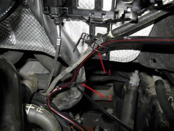
Mounting points:
1) Place the adapter wiring loom in the existing cable holder.
2) Attach the adapter wiring loom with a cable binder on the engine wiring loom.
Feeding-through of grommet:
1) Use the existing opening of the grommet for the feeding-through into the E-box. Seal off the space between the cables with butyl.
To complete the process proceed in the 60 pin engine control unit plug according to the current flow diagram.
A4 (B7) RHD:
Route the adapter wiring loom following the red line.
Overview:
Mounting points:
Attach the adapter wiring loom on the two marked places with cable binders.
Feeding-through of grommet:
Use the grommet of the battery cable for the feeding-through into the plenum chamber.
To complete the process proceed in the 60 pin engine control unit plug according to the current flow diagram.
With engine code BRD and BVA:
Connect the two other cables (without attached contact) according to the current flow diagram with the two cables of boost pressure regulator (use crimp connector). The crimps are still in the E-box. Remove the tape of the engine wiring loom in the E-box.
A6 (C6) LHD
Route the adapter wiring loom following the red line.
Overview:
Feeding-through of grommet:
Remove the blanking plug and fit the grommet of the wiring loom for the feeding-through into the plenum chamber.
E-box feeding-through:
Feed the adapter wiring loom on the marked place into the E-box.
To complete the process proceed in the 60 pin engine control unit plug according to the current flow diagram.
A6 (C6) RHD
The routing to the plenum chamber is identical with the LHD, but in the plenum chamber it must be the other way round.
Warranty accounting instructions
Service number/damage code/manufacturer: 2360 /0039/... (engine control unit update)
Service number/damage code/manufacturer: 2647/0012/… (installation of seal)
Service number/damage code/manufacturer: 9752/0033/… (plug/pins corroded)
a)
Accounting with APOS:
Software update:
Repair operation:
Designation:
Time units:
27 06 89 50
Charge battery
10 TU
01 50 00 00
GFF/guided functions
TU according to diagnosis protocol
Check boost air system:
Repair operation:
Designation:
Time units:
21 41 01 99
Check boost air system
30 TU
Replace exhaust gas recirculation valve:
Repair operation:
Designation:
Time units:
26 39 19 39
Remove and install exhaust gas recirculation valve
70 TU
Remove and install EGR cooler seal
Repair operation:
Designation:
Time units:
26 43 19 99
Remove and install EGR cooler seal
70 TU
Accounting with APOS/2:
Illustration:
Position:
Number:
Designation:
Activity:
Time units:
STA-02
4
915105
Charge battery
90
10 TU
STA-02
1
S00032
Guided fault finding (Software update)
02
TU according to diagnosis protocol
145-xx
x
145737/145738
Check boost air system
98
30 TU
131-xx
x
131501
Replace exhaust gas recirculation valve
55
According to instructions
131-xx
x
131547
Replace EGR cooler seal
55
According to instructions
b) Account according to time used and include operations of APOS and APOS/2.
Parts information
Adapter cable part number (for RHD and LHD):
4F0 971 379 A Audi A4 2,0l 4V TDI 100/103KW
4F0 971 379 B Audi A4 2,0l 4V TDI 120/125KW – engine code: BRD and BVA
4F0 971 379 C Audi A6 2,0l 4VTDI 100/103 KW
The adapter cables are not in included in the parts catalogue.
Customer information
•
The new software includes an improvement of the clutch protection function, as a result the starting characteristics change. The accelerator pedal has been changed so that with the same part load accelerator position less fuel is injected. This leads to a slightly worse acceleration, but the driver can compensate this, for example by pressing the accelerator pedal press pedal further. The injected fuel quantity with full load has not been changed.